The first working version of a fabric tells me whether I can configure its protocols. The first failure test tells me whether I understand how those protocols affect the traffic running through it.
For Project Pivot I built a five-switch Clos topology in Containerlab using virtual SONiC. Two spines provide the transit paths; three leaves connect Linux endpoints. The routed underlay uses eBGP, ECMP, and BFD. On top of that I added a deliberately small EVPN/VXLAN domain with three more endpoints. Each stage had to pass its own validation before I moved on.
The design builds on work I have done with larger production VXLAN/EVPN deployments, but the purpose here was different. I wanted a reproducible environment where I could shut down an active path, impair forwarding without taking the interface down, inspect the route changes, and compare those changes with what a workload reported.
01 / A deliberately small, testable Clos
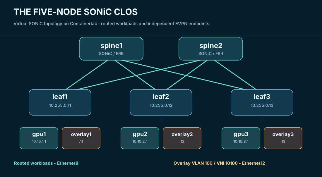
The topology has spine1 and spine2 connected to leaf1, leaf2, and leaf3. Every leaf has a routed link to each spine. Spines are transit devices; the leaves are the network edge for the test endpoints. The routed workloads attach on Ethernet8: gpu1 at 10.10.1.1/31, gpu2 at 10.10.2.1/31, and gpu3 at 10.10.3.1/31.
These names could easily be mistaken for actual GPU systems, so the distinction is worth making: they are Linux containers generating ordinary IP traffic. There were no NVIDIA accelerators on this SONiC fabric, and the results do not represent NCCL or GPU-to-GPU transfers.
A production AI backend may use a pure Layer-3 design without an EVPN Layer-2 overlay. I retained both models in this lab because they test different mechanisms. Routed endpoint prefixes establish the underlay and ECMP behaviors. The overlay exercises distributed MAC learning, VTEP reachability, VXLAN encapsulation, and fault isolation.
02 / Start with underlay reachability and ECMP
Each leaf forms eBGP adjacencies toward the two spines. The fabric advertises loopback and workload reachability across the routed underlay, allowing remote leaves to find the endpoints without extending an access VLAN through the network.
On leaf1, the remote prefix 10.10.2.0/31 appeared through two equal-cost next hops: 10.0.0.0 on Ethernet0 toward spine1 and 10.0.0.2 on Ethernet4 toward spine2. That routing-table evidence established eligible paths. It did not prove that one individual flow would be sprayed evenly over both links.
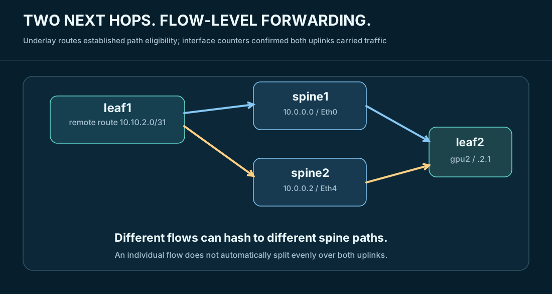
I tested that distinction by observing actual workload paths. Traffic from gpu1 to gpu2 selected spine2; traffic from gpu1 to gpu3 selected spine1. During simultaneous iperf3 workloads, the interface-counter deltas on both leaf1 uplinks confirmed forwarding activity on both paths.
BFD was integrated so a forwarding-path failure could be detected faster than waiting for the ordinary BGP hold timer. That still left several steps between a BFD state change and a resumed application stream: neighbor or path withdrawal, forwarding-table update, ECMP reselection, and transport recovery.
This separation would become visible in the failure measurements.
03 / Add EVPN without confusing it with the underlay
Next I activated the L2VPN EVPN address family across the fabric and added one overlay endpoint to each leaf on Ethernet12. VLAN 100 was mapped to VNI 10100. The overlay hosts used 192.168.100.11/24, .12/24, and .13/24; each had a deterministic MAC beginning with 02:00:00:00:01.
The leaves served as VTEPs with loopback addresses 10.255.0.11, .12, and .13. The spines propagated EVPN routes between leaves but did not terminate VXLAN. In this lab the spines participated in the EVPN control plane; they were not acting as the iBGP route reflectors I had used in a different enterprise design.
The jobs are separate:
- IPv4 eBGP underlay: provides routed reachability to the VTEP loopbacks.
- MP-BGP EVPN: distributes overlay MAC reachability and VNI membership.
- VXLAN data plane: encapsulates and forwards Ethernet frames between leaf VTEPs, using UDP destination port
4789.
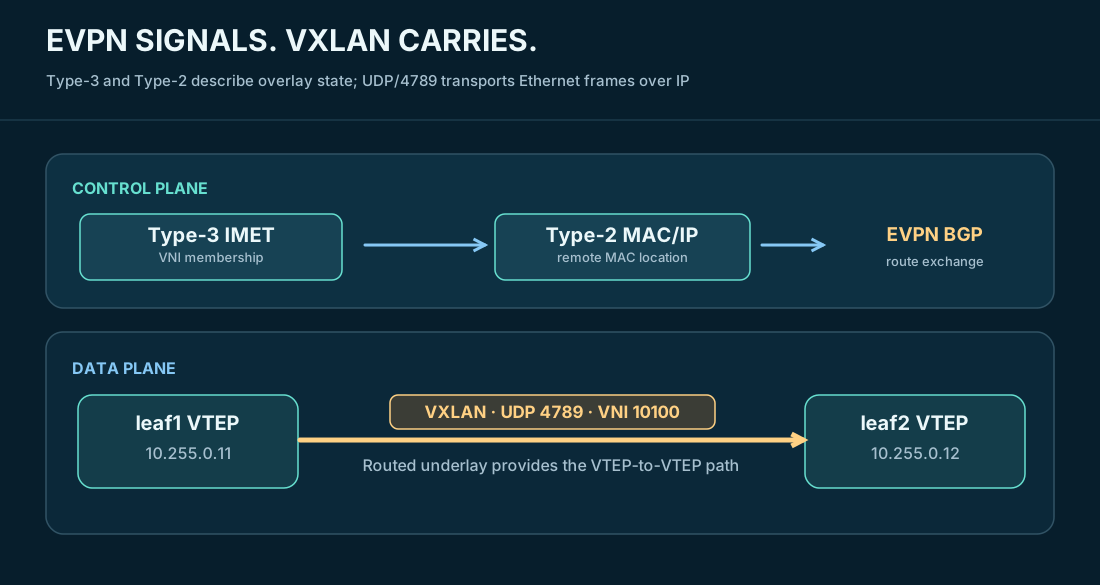
The first routes I checked were Type-3 Inclusive Multicast Ethernet Tag (IMET) advertisements. Each leaf discovered the other two VTEPs for VNI 10100, allowing head-end replication for broadcast, unknown-unicast, and multicast traffic. Type-3 establishes VNI membership; it does not tell me which host MAC resides behind which leaf.
Once the access ports were operational and endpoint traffic started, the leaves advertised Type-2 MAC/IP routes. Leaf1 learned its local overlay1 MAC on Ethernet12 and the two remote MACs through Vxlan0-100, toward 10.255.0.12 and 10.255.0.13. That was the next evidence layer: EVPN had distributed real host-location information rather than merely forming BGP sessions.
04 / Prove encapsulation on the wire, not only in BGP
With BGP and FDB state looking right, I captured overlay traffic. For a packet from overlay1 to overlay2, the evidence showed this outer header:
| Field | Observed value |
|---|---|
| Outer source VTEP | 10.255.0.11 |
| Outer destination VTEP | 10.255.0.12 |
| UDP destination | 4789 |
| VXLAN VNI | 10100 |
| Inner source → destination | 192.168.100.11 → 192.168.100.12 |
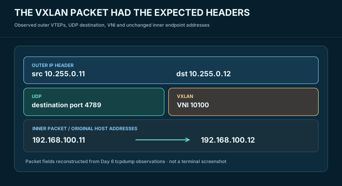
The request and response used different spine paths in one observation. That is legitimate ECMP behavior: the overlay requires reachability between VTEPs, not symmetric physical forwarding through the same spine.
All six directed tests between overlay1, overlay2, and overlay3 passed. At this point I had three independently useful observations: EVPN routes, the forwarding database, and traffic carried in the expected VXLAN encapsulation. An established EVPN adjacency on its own would not have established those outcomes.
05 / Shut down the actual path carrying the workload
A redundant fabric is easier to draw than to validate. For Day 5 I used a test harness that identified the currently selected spine, took down the corresponding leaf uplink, and kept ICMP and TCP traffic running. The harness preserved traceroute, BFD state, next-hop state, packet-loss observations, TCP throughput, restoration, and post-test validation.
For gpu1 → gpu2, the active route used spine2. I disabled leaf1 Ethernet4, forcing the alternate route through spine1. The measurement recorded 1.896 seconds of recovery, a 2.079-second successful-reply gap, nine consecutive lost pings, and two TCP zero-throughput intervals. The existing TCP connection survived the test.
For gpu1 → gpu3, the active route used spine1. I disabled leaf1 Ethernet0, shifting traffic to spine2. Recovery measured 2.056 seconds, with a 2.070-second successful-reply gap, nine lost pings, and two zero-throughput intervals. The TCP session again survived.
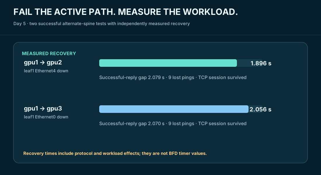
The exact seconds matter less than the explanation. BFD detection is not application recovery. A timer setting can be fast while the end-to-end service still experiences an interruption. The test also verified that after restoration BFD returned up, both ECMP paths became available again, and fabric and workload validation passed.
06 / Failure testing must include the overlay
With basic routed failover proven, I extended fault injection to the overlay: a hard link failure, a silent forwarding impairment, and a VTEP-isolation scenario. I checked BFD and BGP state alongside VTEP routes, EVPN advertisements, FDB entries, and endpoint validation before and after the tests.
The Day 7 repository includes the test-overlay-failures.sh harness and timestamped baseline, incident, and final-state files. Those records are more useful than a success banner alone, because they preserve what changed and what returned to normal. The Day 8 follow-up went deeper into traffic and interface counters, including a 500 Mbit/s UDP workload during a silent-forwarding-path experiment.
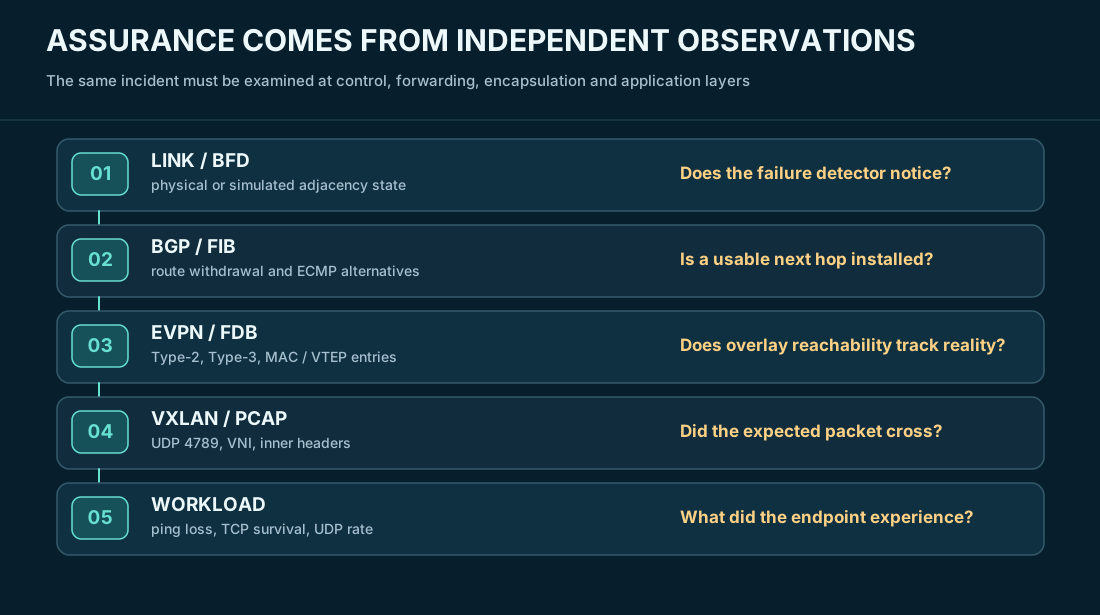
A deliberate silent impairment is especially valuable because the interface can remain administratively and operationally up. An operator who checks only show interfaces status can miss the condition entirely. BFD, route withdrawal, and the behavior of a continuously running workload provide a stronger view.
I treat the scripted results as bounded lab evidence. Virtual SONiC does not reproduce production ASIC buffering, hardware PFC, ECN marking, physical RoCE congestion behavior, or real GPU collectives. Those require different equipment and measurement methods.
07 / Rebuildability is part of operational readiness
The fabric was not left as a collection of manually configured running containers. After Day 6, I destroyed the Containerlab topology and rebuilt it using the source-controlled configuration and bootstrap process. The recreated fabric passed all three independent validators:
FABRIC VALIDATION:   PASS
WORKLOAD VALIDATION: PASS
OVERLAY VALIDATION:  PASS
The repository captured the relevant operational scripts, including bootstrap-fabric.sh, validate-fabric.sh, validate-workload.sh, validate-overlay.sh, test-failover.sh, and the later overlay-failure harness. The test automation was developed with AI assistance, then run, diagnosed, and validated against observable network behavior; it should not be mistaken for hand-authored Python coding experience.
For an SRE-oriented portfolio, that repeatability is as important as a polished topology diagram. It allows a future experiment to start from a known baseline and gives another engineer a reasonable path to verify the results.
08 / What I would carry into a production design
This project made several habits concrete. Before trusting an overlay, I verify VTEP reachability. Before trusting EVPN, I look for the correct route types and FDB entries. Before trusting redundant paths, I identify the path used by a real flow and intentionally remove it. Before declaring recovery, I measure the application and check that full redundancy has returned.
I would also apply more explicit production controls than a small isolated lab requires: BGP neighbor authentication where supported and operationally appropriate, management-plane isolation, prefix and route-policy filtering, change-reviewed configuration, restricted telemetry access, and rollback plans. If an EVPN overlay is needed at all, its VLAN/VNI and tenant boundaries need an explicit security model. A GPU backend network does not automatically need Layer 2 extension merely because VXLAN is familiar.
The major lesson from this build is operational, not cosmetic: the fabric is testable because routing state, overlay state, packet behavior, and workload behavior were all measured independently. That is the foundation I want before introducing the harder congestion and RDMA questions that come next.
Evidence trail
The underlying experiment records are maintained in the Project Pivot Git repository on fabric-lab-1 under fabric/sonic-clos/:
docs/day5-workload-failover.md: ECMP path selection, active-path link shutdowns, timed recovery, TCP survival, and test script behavior.docs/day6-evpn-vxlan.md: VNI/VTEP mapping, EVPN route advertisements, forwarding database, tcpdump encapsulation, and reproducible rebuild.docs/day7-evpn-vxlan-failure-testing.mdandevidence/day7-overlay-failures/: overlay impairment and post-test state captures.- Day 8 workload convergence evidence and Day 9 monitoring work provide the operational follow-through; they are not prerequisites for the specific Day 5/6 claims above.
The diagrams are explanatory reconstructions. They are not direct screenshots, raw packet captures, or proof of physical ASIC behavior.
Protocol and platform references
- SONiC architecture, official project wiki
- FRRouting 10.4 BGP and EVPN operations
- RFC 7432: BGP MPLS-Based Ethernet VPN
- RFC 8365: Network Virtualization Overlay Solution Using EVPN
- RFC 7348: Virtual eXtensible Local Area Network (VXLAN)